How Residential Electrical Wiring Delivers Safe Power Throughout Your Home
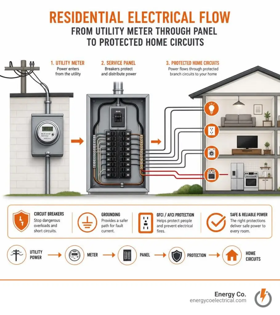
Residential electrical wiring carries power from the utility meter to your service panel, then through protected branch circuits to lights, appliances, switches, and receptacles. For a safe system, homeowners should:
- Turn off the correct breaker and test for voltage before touching any wire.
- Match the breaker size, wire gauge, and circuit load. For example, 14 AWG copper is generally used on 15-amp circuits, while 12 AWG is used on 20-amp circuits.
- Use GFCI and AFCI protection where required, keep every splice inside an approved electrical box, and call a licensed electrician for panel work, new circuits, damaged wiring, or repeated breaker trips.
In a typical Chicago-area home, electricity enters through the meter and main service equipment, then the panel divides it into 120-volt and 240-volt circuits. Circuit breakers stop dangerous overloads, while grounding provides a safer path for fault current. Understanding these basics helps you spot warning signs early, especially in older homes with aging panels, ungrounded outlets, aluminum wiring, or outdated fuse equipment.
I am Michał Napieralski of Energy Co., where our licensed team handles residential electrical wiring, panel upgrades, circuit breaker replacement, wiring repairs, inspections, outlets, switches, and EV charger installations across the Chicago suburbs. The sections ahead explain what each part does, which safety rules matter most, and when a professional repair is the right call.
Residential electrical wiring glossary:
Fundamentals of Residential Electrical Wiring: Concepts and Anatomy
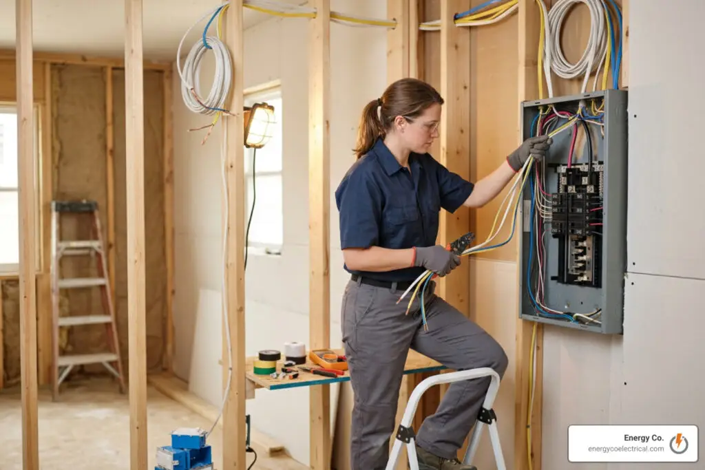
To make sense of the wires running behind your drywall, start with fundamental electrical theory. Electricity functions like water flowing through pressurized pipes: potential pushes electrons along conductive paths to do useful mechanical or thermal work. Reviewing A Beginner Breakdown of Home Electrical Wiring and Safety can help clarify these core principles before examining specific hardware.
Voltage, Current, and Essential Electrical Terms
Three basic measurements govern every home electrical circuit:
- Voltage ($V$): The electrical pressure pushing electrons through a conductor, measured in volts. Standard North American homes use a 120V/240V split-phase setup.
- Current ($I$): The volume of electron flow passing a point per second, measured in amperes (amps).
- Resistance ($R$): The opposition to current flow within a material, measured in ohms ($Omega$).
These three factors connect through Ohm’s Law ($V = I times R$) and the basic electrical power equation:
$$text{Watts (Power)} = text{Volts} times text{Amps}$$
For example, a 120V circuit carrying 15 amps can supply up to 1,800 watts. Continuous loads—devices drawing power steadily for three hours or longer, such as baseboard heaters—must stay within 80% of the circuit’s total capacity (1,440 watts on a 15A branch).
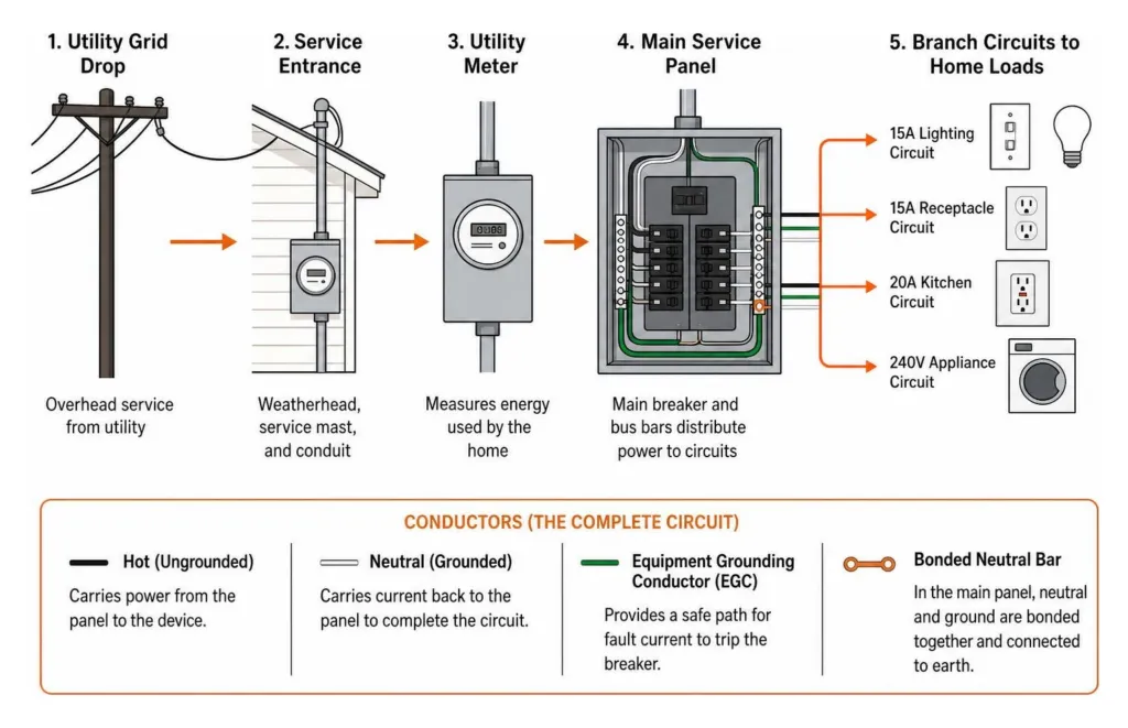
Every complete circuit requires a closed loop:
- Hot (Ungrounded) Conductor: Delivers voltage from the panel to the device.
- Neutral (Grounded) Conductor: Carries current back to the panel to complete the circuit.
- Equipment Grounding Conductor (EGC): Carries zero current during normal operation. If a loose hot wire contacts a metal fixture or appliance chassis, the ground path channels the fault current directly back to the panel, tripping the breaker rather than shocking an occupant.
- Bonded Neutral Bar: At the main service panel, the neutral bus and grounding bus connect together and link to earth through grounding electrode conductors (such as copper ground rods and metallic incoming water lines).
How Power Flows: From Service Drop to Circuit Breakers
Residential power starts at the utility transformer, which delivers two 120V energized lines and one neutral conductor through an overhead service drop or underground lateral. It flows through the glass utility meter on your exterior wall directly into the service entrance panel.
The main breaker (often rated for 100A, 150A, or 200A) acts as the primary shut-off for the whole house. Beneath it run two solid copper or aluminum bus bars, each energized to 120V relative to ground, but 180 degrees out of phase with each other.
- 120-Volt Branch Circuits: Created by snapping a single-pole circuit breaker into either bus bar.
- 240-Volt Branch Circuits: Created by installing a double-pole breaker that spans both bus bars simultaneously (supplying heavy loads like central air conditioners, electric ranges, and water heaters).
Learning more about Demystifying Your Home Electric Panel Without Getting Shocked will help you read panel labels, understand bus bar distribution, and locate individual branch breakers.
Types of Cables, Conductor Gauges, and Color Codes
Residential wiring relies on copper conductors due to copper’s electrical conductivity, tensile strength, and resistance to thermal expansion. Selecting the right wire size and jacket construction prevents overheating behind finished walls. To explore wire types further, consult A Complete Guide to Residential Wiring Types and Installation.
| Conductor Size (AWG) | Maximum Overcurrent Protection (Amps) | Continuous Load Limit (80% / 120V) | Typical Residential Applications |
|---|---|---|---|
| 14 AWG | 15 A | 1,440 W | General bedroom lighting, living room receptacles, smoke alarms |
| 12 AWG | 20 A | 1,920 W | Kitchen small appliance circuits, bathroom receptacles, laundry outlets |
| 10 AWG | 30 A | 2,880 W (at 120V) / 5,760 W (240V) | Electric water heaters, clothes dryers, central AC condensers |
| 8 AWG | 40 A | 7,680 W (at 240V) | Electric cooktops, high-output subpanels, heat pumps |
| 6 AWG | 50 A–60 A | 9,600 W–11,520 W (at 240V) | Electric ranges, large subpanel feeds, 48A hardwired EV chargers |
Understanding Wire Gauges and Ampacity Ratings in Residential Electrical Wiring
The American Wire Gauge (AWG) system works inversely: smaller numbers indicate larger conductor diameters. As diameter increases, resistance decreases, allowing the conductor to carry higher current without overheating.
Matching overcurrent protection to conductor ampacity prevents conductors from melting their insulation before a breaker trips. Standard reference publications like the 2026 Electrical Wiring Guide outline these conductor sizing rules.
Voltage drop is another key sizing factor. When a branch circuit runs longer than 100 feet from the main panel, electrical resistance causes a gradual voltage decline. Upsizing conductors (for example, using 12 AWG instead of 14 AWG on a long 15A run) prevents connected motors and sensitive electronics from overheating or malfunctioning.
NM-B, UF-B, and Conduit-Bound THHN Conductors
Different household locations require specific cable jackets:
- Type NM-B (Non-Metallic Sheathed): Commonly known as Romex, NM-B features PVC-insulated conductors and a bare copper ground encased in a flame-retardant outer jacket. It is rated for dry, interior installations within wall studs, ceiling joists, and floor framing. The outer sheathing is color-coded: White = 14 AWG, Yellow = 12 AWG, Orange = 10 AWG.
- Type UF-B (Underground Feeder): Designed for wet locations and direct burial in soil without conduit. Unlike NM-B, UF-B’s solid vinyl jacket completely encapsulates each insulated conductor and ground wire, shielding them from moisture and soil acids.
- Type THHN/THWN Single Conductors: Individual thermoplastic high-heat nylon-coated wires. They cannot be run exposed through stud cavities and must be pulled through metal or PVC raceways (such as EMT conduit).
In the City of Chicago and several Cook County jurisdictions, building codes generally prohibit exposed or concealed NM-B cable in residential living spaces, requiring metal conduit (EMT) and THHN conductors instead to maximize physical protection against accidental punctures and structural fires.
Standard Color Coding and Conductor Identification
Standard conductor insulation colors help prevent crossed polarities and short circuits:
- Black: Primary hot conductor carrying 120V potential.
- Red: Secondary hot conductor used in 240V circuits, multi-wire branch circuits, or as the traveler wire in three-way switch setups.
- White (or Gray): Grounded neutral conductor providing the return path.
- Bare Copper or Green: Equipment grounding conductor.
- Blue and Yellow: Typically used in conduit systems for specialized switch legs, three-way travelers, and ceiling fan controls.
When wiring single-pole switches and standard duplex receptacles, remember the traditional electrician rule: “Black to brass, white to light (silver), green to ground.”
If a white insulated wire is repurposed as an ungrounded switch traveler in a switch loop, code mandates re-identifying both ends using black or red electrical tape.
Essential Safety Devices, Box Sizing, and Code Standards
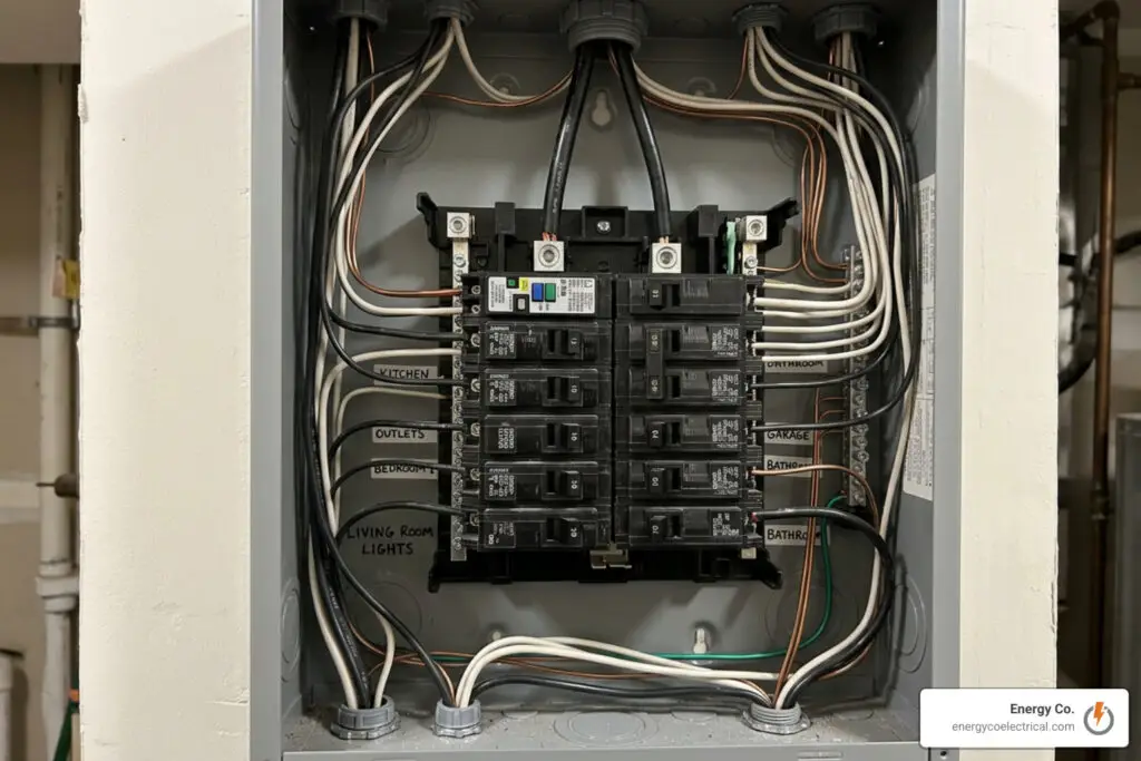
Modern electrical safety relies on proper physical containment and dedicated protective devices that respond to heat, ground faults, and arcing conditions. Standard reference guides, such as the widely referenced Electrical Wiring Residential, detail how these modern safety devices protect properties from fire hazards.
Calculating Electrical Box Fill Capacity
Overcrowded electrical boxes trap heat and can pinch conductor insulation against metal edges. The National Electrical Code (NEC) establishes volume requirements based on conductor size:
- 18 AWG: 1.50 cubic inches per conductor
- 14 AWG: 2.00 cubic inches per conductor
- 12 AWG: 2.25 cubic inches per conductor
- 10 AWG: 2.50 cubic inches per conductor
To calculate the required box volume, count the components inside:
- Conductors: Count each hot and neutral conductor passing through or terminating in the box as 1. (Do not count pigtails that originate and stay within the box).
- Clamps: Add 1 conductor allowance if internal cable clamps are built into the box.
- Devices: Add 2 conductor allowances for each yoke or strap containing a switch or duplex receptacle.
- Grounding Wires: Add 1 conductor allowance for all equipment grounds combined (plus an additional 0.25 allowance for each ground wire beyond four under recent editions).
$$text{Required Minimum Box Volume} = text{Total Conductor Equivalents} times text{Volume Allowance per Gauge}$$
Using a standard plastic box stamped with its volume (such as 18.0, 20.3, or 22.5 $text{in}^3$) ensures your installation complies with box-fill safety rules.
GFCI and AFCI Protection Requirements
- Ground-Fault Circuit Interrupters (GFCI): GFCIs continuously monitor current balance between the hot and neutral wires. If an imbalance as small as 4 to 6 milliamperes occurs—indicating current is leaking through water or a human body—the GFCI disconnects power in milliseconds. GFCIs are required in all wet or damp locations: kitchen countertops, bathrooms, crawl spaces, unfinished basements, garages, exterior receptacles, and anywhere within 6 feet of a sink edge.
- Arc-Fault Circuit Interrupters (AFCI): AFCIs use microprocessors to detect the electrical signature of arcing, which occurs when loose screw terminals, cracked wire insulation, or wall nails puncture a cable. AFCIs cut circuit power before these arcs ignite dry framing lumber. Modern residential codes mandate AFCI protection for branch circuits serving bedrooms, living rooms, dining rooms, hallways, and family gathering spaces. Local requirements may also apply, as outlined in The Shocking Truth About Chicago AFCI Requirements.
Best Practices, Common Mistakes, and When to Call a Pro
A clean installation makes future troubleshooting straightforward and helps keep your home safe. Following a structured set of best practices during initial rough-in work prevents costly corrections during final inspection.
- Support NM-B cable with approved staples within 12 inches of every enclosure and at intervals no greater than 4.5 feet along studs.
- Leave at least 6 inches of free conductor length extending beyond the front face of every device box for clean terminations.
- Maintain clear 30-inch-wide by 36-inch-deep working clearances in front of all electrical panels.
- Use tamper-resistant (TR) receptacles with internal shutters throughout living areas to protect young children from electrical shocks.
Avoiding Dangerous Installation Errors in Residential Electrical Wiring
Even minor oversights during wiring can cause component damage or fire hazards. Reviewing Electrical Repairs: Dos and Don’ts for Beginners can help you identify hazardous wiring conditions before starting work.
- Mismatched Breaker and Wire Gauges: Connecting 14 AWG wire to a 20-amp breaker is dangerous. The thin wire could overheat and cause a fire before the oversized breaker trips.
- Unprotected Splices (Flying Splices): Every wire connection must be secured with listed wire nuts or lever connectors inside an accessible, covered junction box. Concealing splices behind drywall violates building codes.
- Back-Stabbed Receptacle Terminals: Pushing solid copper wires into spring-loaded push-in terminals on the back of cheap receptacles can lead to loose connections over time under thermal cycling. Use side screw terminals or clamp-plate designs instead.
- Missing Cable Clamps and Bushings: Running cables directly through sharp knockouts in metal junction boxes without protective connectors will eventually wear through the insulation.
Essential Tools and Safe Working Protocols
Safe electrical work requires the proper tools and procedures:
- Non-Contact Voltage Tester: Tests for live electrical fields around cables and switch terminals without touching bare metal.
- Precision Wire Strippers: Cuts clean insulation jackets without nicking the copper conductor underneath.
- Lineman’s and Long-Nose Pliers: Twists solid conductors together into tight splices and shapes secure terminal loops.
- Digital Multimeter (CAT III Rated): Accurately reads line-to-neutral, line-to-line, and line-to-ground AC voltages.
Always verify your voltage tester on a known live source, test the target wire to confirm it is de-energized, and then re-test on the known live source before handling any conductors.
Frequently Asked Questions About Residential Electrical Wiring
What is the difference between 12-gauge and 14-gauge wire?
12-gauge wire is thicker than 14-gauge wire and can safely carry up to 20 amps, supporting loads up to 1,920 continuous watts at 120 volts. 14-gauge wire is rated for a maximum of 15 amps (1,440 continuous watts at 120 volts). While 14-gauge wire is suitable for general household lighting and standard bedroom outlets, 12-gauge wire is required for heavier-demand areas like kitchen countertops, bathrooms, and laundry circuits.
Where are GFCI and AFCI outlets required in a home?
GFCI protection is mandatory in areas where water and moisture create an elevated risk of ground faults, including kitchens, bathrooms, unfinished basements, crawl spaces, garages, outdoor outlets, and anywhere within 6 feet of sinks. AFCI protection is required across finished living areas—such as bedrooms, living rooms, dining rooms, family rooms, and hallways—to monitor for electrical arcing in damaged cords or wall wiring. Many modern installations use dual-function AFCI/GFCI circuit breakers at the service panel to provide both protections from a single device.
Can I do my own home electrical wiring or should I hire an electrician?
Homeowners can often handle simple tasks like swapping a light fixture or replacing a single outlet on a de-energized circuit. However, new circuit installations, panel upgrades, whole-house rewiring, and subpanel additions require building permits and professional training. In areas like Chicago and Cook County, local building codes mandate metal conduit systems that require professional pipe-bending and pulling equipment. Hiring a licensed, insured contractor ensures your electrical system complies with current NEC standards and local building codes.
Conclusion
A home’s electrical wiring works behind the scenes to deliver reliable power throughout your living space. From the moment high-voltage electricity enters the utility meter to its journey through the breaker panel, branch circuits, and safety devices, each component must match in gauge, ampacity, and enclosure protection to prevent hazards.
Whether you are updating a vintage bungalow in Chicagoland, dealing with persistent breaker trips, adding dedicated appliance lines, or planning a service panel replacement, work with a certified professional. Explore our comprehensive Residential Electrical Services to schedule an on-site safety inspection, system repair, or complete home rewiring with the licensed team at Energy Co.