What an Electrical Installation and Maintenance Module Teaches
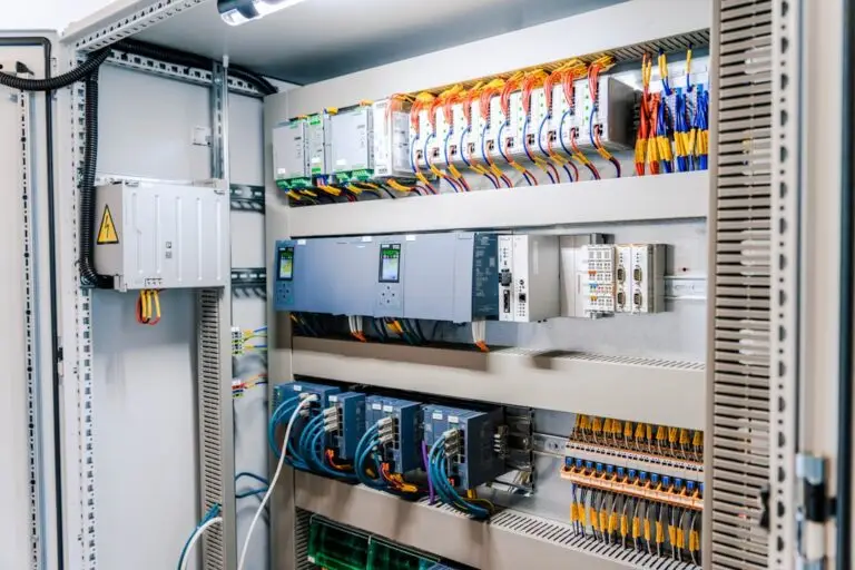
An electrical installation and maintenance module is a structured training guide for learning the basics of safe wiring work. If you are looking to download or use one, start with modules that cover these five core areas:
- Preparing electrical supplies, materials, and tools
- Measuring and making basic calculations
- Reading electrical symbols, drawings, and plans
- Maintaining and storing tools and equipment
- Practicing occupational safety and health
These lessons give new technicians a practical foundation: choosing the right tool, checking materials before a job, reading a wiring diagram, making safe connections, and spotting hazards before work begins. Introductory Grade 7/8 modules are exploratory courses that can lead toward Electrical Installation and Maintenance NC II training, but real installation, repairs, and work on energized systems require proper supervision, licensing, and local code compliance.
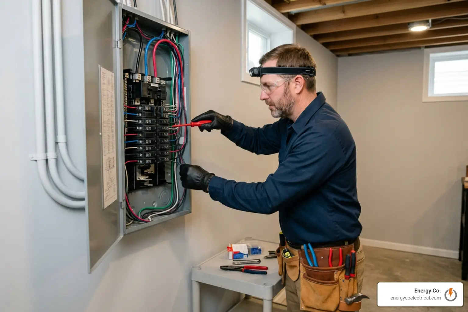
For Chicago-area property owners, these same basics explain why qualified electricians inspect wiring, protection devices, tools, and plans before repairing an outage or upgrading older electrical equipment.
I am Michał Napieralski of Energy Co., an electrician serving Schaumburg and the Chicago suburbs with residential and commercial wiring, panel upgrades, inspections, and maintenance. My field experience helps connect each electrical installation and maintenance module topic to the checks and safe work practices used on real service calls.
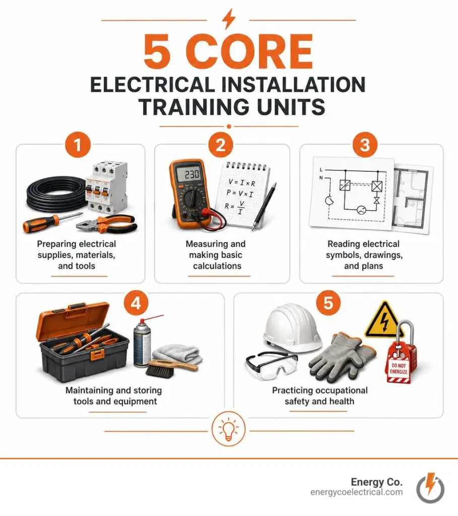
Electrical installation and maintenance module basics:
Core Competencies in the Electrical Installation and Maintenance Module
The journey into electrotechnical trades starts with structured, self-paced competency units. Whether working through secondary vocational exploratory modules or pursuing a formal Level 2 Diploma in Electrical Installations (2365-02), every aspiring technician must master standard operational standards before ever touching a live service panel.
The exploratory training framework bridges pure academic theory and practical workshop execution. By mastering the basics of electrical installation work, students learn how individual components interact to deliver safe, reliable electricity throughout residential, commercial, and industrial structures.
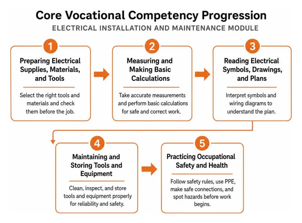
Sourcing Tools and Materials in an Electrical Installation and Maintenance Module
A technician is only as good as their preparation. Before turning a single screw, trainees must identify 16 common electrical hand tools, striking implements, and hardware supplies:
- Driving Tools: Standard/flat screwdrivers, Philips screwdrivers, stubby screwdrivers (designed specifically for tight, restricted spaces), and Allen wrenches/screwdrivers for hex-socket fasteners.
- Pliers & Cutting Tools: Combination pliers (lineman’s pliers) for gripping and twisting heavy conductors, side-cutting pliers for trimming leads, long-nose pliers for fine terminal adjustments, wire strippers (calibrated for #10 to #16 AWG conductors), and electrician’s knives.
- Striking & Drilling Equipment: Claw hammers, ball-peen hammers, and portable electric drills with chuck capacities typically ranging from 1/4 inch to 3/8 inch.
- Boxes & Enclosures: Octagonal junction boxes (where conductors are spliced and joined) and rectangular utility boxes (used to house switches and duplex receptacles).
- Raceways & Conduits: Rigid Non-Metallic Conduits (PVC), Corrugated Plastic Conduits (CPC or flexible non-metallic conduit), and metallic conduits along with their respective clamps, straps, and connectors.
- Circuit Protection & Wiring Devices: Plug/cartridge fuses, molded case circuit breakers, flush and surface-type convenience outlets, male plugs, and single-gang or multi-gang wall switches.
Handling jobs in a professional electrical contracting environment also requires strict inventory documentation. Modules introduce four standard administrative forms:
- Purchase Requisition Form: Sourced by an apprentice or department to formally request needed supplies from the warehouse or supply shop.
- Inventory of Materials Form: Used to track existing on-hand stock, cataloging functional vs. non-functional items and flagging depleted hardware.
- Job Order / Work Order Form: Outlines the technical instructions, location, authorized personnel, and scope of work for an assigned electrical task.
- Borrower’s Form (Slip): Logs accountability when specialized measuring instruments or high-value power tools are checked out of the tool room.
Mensuration, Calculation, and Multitester Operation
Precise measurement ensures electrical conductors fit raceways without exceeding allowable conduit fill capacities, and prevents terminal overheating due to incorrect wire sizing.
Technicians must fluidly convert between the English system and Metric linear units:
- $1text{ inch} = 2.54text{ cm} = 25.4text{ mm}$
- $1text{ foot} = 12text{ inches} = 30.48text{ cm}$
- $1text{ yard} = 3text{ feet} = 36text{ inches} = 91.44text{ cm}$
- $1text{ meter} = 100text{ cm} = 1,000text{ mm}$
When measuring wire thickness, magnetic conductors, and sheet materials, standard rulers are supplemented by precision micrometers and standard American Wire Gauge (AWG) circular wire gauges.
| Measuring Tool / Instrument | Primary Function | Typical Applications |
|---|---|---|
| Test Light | Quick visual go/no-go voltage check | Verifying live receptacle power |
| Pull-Push Rule | Flexible tape for linear measurements | Measuring conduit runs and rough-in heights |
| Micrometer | Ultra-high precision linear micrometer | Measuring bare conductor diameters |
| Wire Gauge (AWG) | Circular slotted diameter assessment | Sizing solid conductors from #0 to #36 AWG |
| Ammeter | In-series electrical current intensity measurement | Measuring branch circuit load current |
| Clamp Ammeter (Tong-Tester) | Inductive non-contact current measurement | Measuring live lines without breaking the circuit |
| Voltmeter | Parallel potential difference measurement | Measuring voltage supply (e.g., 120V / 240V) |
| Volt-Ohmmeter (VOM / Multitester) | Combined multi-parameter testing | Resistance, voltage, and continuity testing |
Reading an analog multitester requires understanding its scale divisions and calibration protocols. When using an ohmmeter, always short the test probes together and adjust the Zero-Ohm Adjustment Knob until the indicator pointer rests directly over the $0,Omega$ mark on the far right of the graduated scale.
If measuring resistance using the $R times 10$ range setting and the needle points to $15$, multiply the reading by the range factor ($15 times 10 = 150,Omega$). When checking AC or DC voltage, read from left to right on the corresponding voltage scales, selecting a range higher than the anticipated system voltage to protect the delicate meter movement.
Interpreting Technical Drawings and Wiring Schematics
Electrical blueprints translate structural intentions into physical reality. Technicians work with three common technical representations:
- Pictorial Diagrams: Visual sketches showing the external physical appearance of components, light fixtures, and connections (frequently used in entry-level instructional guides).
- Schematic Diagrams: Highly structured technical diagrams that use standardized electrical symbols to show how a circuit functions electrically, rather than its physical geographic layout.
- Electrical Plans: Top-down architectural floor plans illustrating the exact spatial layout of lighting outlets, switches, duplex convenience receptacles, service entrance gear, and distribution panelboards throughout a dwelling.
Technicians must instantly recognize standardized drafting symbols:
- Circle with four radial spokes: Incandescent ceiling lamp outlet
- Circle with two parallel lines through it: Duplex convenience outlet (flush type)
- Circle with the letter “S” and subscript (e.g., $S1$, $S2$, $S_3$): Single-pole switch, two-gang switch, or three-gang switch
- Solid Line: Concealed wiring run in ceiling or wall
- Interrupted / Dashed Line: Concealed wiring run in floor or exposed run
Modules also teach the core functional difference between series circuits (where current flows through a single unbroken path, causing all downstream loads to drop out if one fails) and parallel circuits (where each appliance or fixture receives full line voltage across independent branch loops, serving as the standard for all modern structural wiring).
Practical Wiring Techniques, Splices, and Project Execution
Translating technical theory into physical wiring requires meticulous dexterity. Removing insulation—commonly referred to as wire skinning—must be executed without scoring, nicking, or severing conductor strands. Even a slight nick from an electrician’s knife or misaligned wire stripper creates a mechanical stress riser that causes localized electrical resistance, hot spots, and eventual wire fatigue.
Our technicians follow these practical standards across all residential and commercial jobs. For a full breakdown of trade workflows, consult our practical guide to electrical installation.
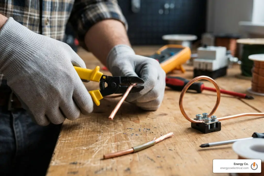
When attaching skinned solid conductors to screw terminals on switches or duplex receptacles:
- Strip approximately 1 to 1.5 inches (25 mm to 38 mm) of insulation.
- Use long-nose pliers to form a smooth, semicircular wire loop.
- Hook the loop around the terminal screw strictly in a clockwise direction. As the screw is tightened down clockwise, the rotational friction pulls the copper loop tighter around the shank rather than opening or ejecting it.
Essential Wire Splices and Joint Terminations
Different electrical splices serve distinct mechanical and electrical needs depending on physical strain and installation enclosures:
- Rat Tail (Pig Tail) Joint: Used to connect two or more conductors inside junction boxes and utility boxes. Conductor ends are stripped approximately 50 mm, held parallel, and twisted 5 to 7 times. This joint provides zero mechanical tensile strength and must only be used inside enclosed enclosures where the wires are not subjected to physical pulling.
- Western Union Short-Tie Splice: Designed to join two conductors in interior runs where slight mechanical tension is present.
- Western Union Long-Tie Splice: Engineered for extensive outdoor spans and overhead wiring subject to heavy tensile stress. Conductors are stripped 75 mm to 80 mm, crossed mid-span, wrapped with 4 to 6 long center twists, and finished with 4 to 5 tight outer locking wraps on each side.
- Knotted Tap Joint: Used where a branch or tap conductor is spliced onto an unbroken continuous main conductor under significant tensile load. The tap wire is tied in a locking knot over the main conductor before wrapping.
- Plain Tap Joint: Connects a tap wire to a continuous running conductor under minimal to no mechanical strain.
- Aerial Tap Joint: Commonly used for temporary power taps (such as construction site branch lines) where the tap wire needs freedom of movement without fatiguing the main conductor.
- Wrapped Tap (Tee) Joint: Utilized when branching off large-gauge, heavy conductors that are too thick to easily knot or twist directly.
- Duplex Cross Joint: Used to tap two simultaneous branch circuits off a continuous main feeder conductor run.
Step-by-Step Project Plan: Assembling an Extension Cord
The standard practical benchmark project in foundational training modules is the assembly of a heavy-duty portable extension cord.
Step-by-Step Procedure:
- Prepare the Cord Ends: Split the duplex flat cord jacket approximately 8 cm (3 inches) at both terminal ends without damaging the internal individual conductor insulation.
- Skin the Conductors: Strip 1.5 cm to 2.5 cm of insulation from each conductor end.
- Tie the Underwriter’s Knot: Inside the male plug cavity, form a standardized Underwriter’s Knot. Bend the left strand downward and behind the main cord; bend the right strand across the front, loop it through the left eyelet, and draw both ends tight. This knot prevents mechanical pulls on the power cord from transferring tensile strain directly to the terminal screw connections.
- Terminate to Male Plug: Form clockwise loops or crimp eyelet connectors onto the bare copper, fastening them securely under the terminal screws inside the plug housing.
- Terminate to Convenience Receptacle: Connect the opposite conductor ends to the surface convenience outlet, fastening the hot (brass) and neutral (silver) screws securely.
- Quality & Safety Assessment: Before energizing, use a multitester set to the $R times 1$ ohmmeter range to test for zero resistance (continuity) along each line and infinite resistance (no short circuits) between hot and neutral blades.
Performance is rated using structured assessment rubrics covering four metrics: Accuracy (40%), Workmanship/Handling (30%), Safety Practices (20%), and Speed (10%).
Preventive Maintenance, Tool Care, and Workshop 5S
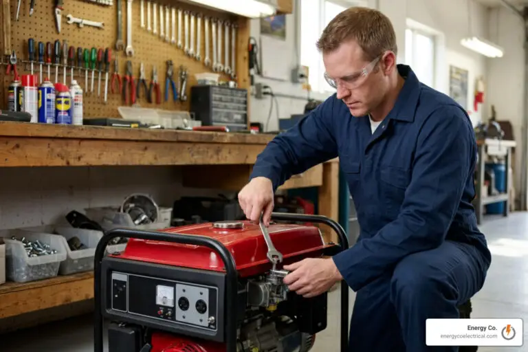
A technician’s tool kit represents both an investment and a first line of defense against physical injury. Routine preventive maintenance prevents accidental tool slippage, electric shocks from damaged insulation, and early equipment failure. For additional safety considerations, review our beginner breakdown of home electrical wiring and safety.
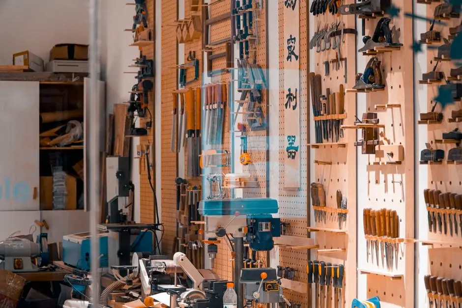
Daily tool maintenance protocols center on three core actions:
- Visual & Functional Inspection: Check screwdriver shafts for bending and insulation handles for cracking. Inspect pliers for chipped cutting jaws, worn pivot joints, and damaged insulating grips. Power cords on portable electric drills must be inspected for exposed copper, cuts, and loose strain-relief boots.
- Cleaning Solvents & Lubrication: Use nonpolar and specialized solvents to remove grease, grime, and dust without degrading plastic housings. Apply anti-rust lubricant spray to metal pivot joints on lineman’s pliers and adjustable wrenches to reduce friction and displace moisture. When pulling long wire runs through conduit, always use specialized, non-damaging wire-pulling lubricant.
- Systematic Workshop 5S Application:
- Sort (Seiri): Separate necessary tools from broken, obsolete, or non-functional items. Tag and discard damaged gear.
- Systematize (Seiton): Arrange tools logically in labeled shadow boards, slotted racks, and fitted toolboxes so every item has a dedicated, accessible location.
- Sweep (Seiso): Clean the work area, sweep metal shavings and insulation scraps, and wipe down tools immediately after completing a job.
- Sanitize (Seiketsu): Maintain high workshop housekeeping standards by scheduling routine maintenance and safety audits.
- Self-Discipline (Shitsuke): Build personal habits of returning tools to their designated spots, inspecting test leads before use, and following equipment handling instructions.
Occupational Health, Risk Assessment, and Safety Standards
Electrical work carries inherent physical and environmental risks. Vocational curricula teach the difference between a hazard (anything with the potential to cause harm, such as an exposed 120V busbar or frayed cable) and a risk (the likelihood and severity of harm occurring from exposure to that hazard).
Workplace hazards fall into distinct categories:
- Electrical Energy: Arc flash, electric shock, secondary arc blast burns, and electrical fires.
- Physical Hazards: Slips, trips, falls from ladders, and entanglement with rotary tools.
- Chemical Hazards: Corrosive battery acids, cleaning solvents, and synthetic lubricants.
- Ergonomic Hazards: Awkward postures while working in attics, repetitive twisting, and heavy cable pulling.
- Environmental & Legacy Contaminants: Asbestos insulation and lead dust frequently encountered in historic structures.
Mitigating these hazards follows the standard Hierarchy of Controls, moving from elimination and engineering isolations down to administrative rotations and Personal Protective Equipment (PPE).
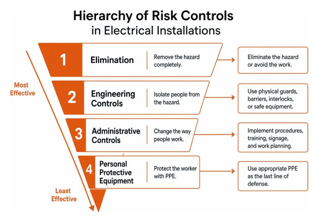
Vocational training aligns directly with professional industry standards, including the Level 3 Electrotechnical Qualification frameworks, which mandate rigorous risk assessment before energizing structural installations.
Safety Protocols Taught in an Electrical Installation and Maintenance Module
Safe isolation is the most critical procedure taught in electrical modules. Before beginning any installation, repair, or modification work:
- Identify the circuit controlling the target installation.
- Disconnect the supply by opening the dedicated circuit breaker or isolator switch.
- Lock out and tag out (LOTO) the disconnection device to prevent unauthorized re-energization.
- Verify testing instrument integrity using a proving unit or known live voltage source.
- Test the isolated circuit across line-to-neutral, line-to-ground, and neutral-to-ground to confirm zero energy state.
- Re-verify testing instrument integrity on the proving unit to confirm the tester did not fail during the dead check.
Beyond electrical safety, local building regulations demand strict compliance with structural protection mandates. In communities throughout the Chicagoland area—such as Streamwood, Schaumburg, and Cook County—installations must follow strict municipal building codes and regulations. For example, local codes often mandate rigid or thin-wall metallic conduit (EMT) rather than exposed non-metallic sheathed cable to protect conductors from mechanical damage and rodent penetration.
Frequently Asked Questions About Electrical Training Modules
What career qualifications follow an introductory electrical module?
Completing an exploratory Grade 7/8 or foundational vocational module prepares learners for National Certificate Level I (NC I) and Level II (NC II) certifications. NC II holders are qualified to perform residential and commercial electrical installation, rough-in wiring, raceway fabrication, panel terminations, and basic diagnostic testing under the supervision of a licensed master electrician or electrical contractor.
Why must terminal wire loops be fastened clockwise on screws?
Terminal screws tighten in a clockwise direction. Placing the wire loop clockwise ensures that the mechanical friction of the turning screw head draws the loop inward, creating a tight, compressed connection around the screw shank. Fastening a loop counter-clockwise causes the screw head to catch the loose conductor tail, opening the loop, ejecting the wire, and creating a loose, high-resistance connection that can cause arcing and electrical fires.
What is the practical difference between a fuse and a circuit breaker?
Both components serve as overcurrent protective devices designed to interrupt abnormal current flow during overload or short-circuit conditions.
- Fuse: Contains a calibrated metal alloy melt link that physically melts (blows) when current exceeds its threshold. Once blown, a fuse cannot be reset and must be discarded and replaced.
- Circuit Breaker: Uses an electromechanical or bimetallic thermal trip mechanism that automatically opens the internal contacts when an overload or short circuit occurs. After the underlying fault is cleared, the breaker can simply be reset by hand without replacing components.
Master Electrical Work with Professional Execution
Completing a foundational training module builds essential technical knowledge: selecting the right tools, reading diagrams accurately, making clean wire splices, and following basic safety protocols. However, real-world building wiring—especially panel upgrades, high-voltage equipment, and historic home rewiring—demands years of field experience and licensed expertise.
If your residential or commercial project requires licensed, code-compliant execution across Schaumburg, Chicago, or the Northwest Suburbs, trust the licensed professionals at Energy Co. for top rated electrical installation service in Chicago. Whether you need whole-house rewiring, backup generator installations, or 24/7 emergency diagnostic repairs, we deliver guaranteed workmanship backed by local expertise. Contact Energy Co. today to schedule your service.